


- Changchun Rongde Optics
- Co.,Ltd.
- Add:No.1666 Yaan Road,
- North Lake Development District,
- Changchun 130102,China
- Tel:86-431-81881745
- Fax:86-0431-85256892
- E-mail:rongdecui@roundss.net
- Skype:adacui_roundss
Company News
Current position :Home > News > Industry News
Rotary encoder principle/robot sensor applicaiton!
Changchun Rongde Optics Co.,Ltd. Release time:2016/6/16 Browse:1101Encoder principle, robot sensors
1. Outline
In the terminology relating to industrial robots function, "internal" measurement function is defined as the measurement of the robot itself a state function, the so-called internal sensor is to realize elements of the function, linear displacement particular detected object articulated, angular displacement geometry, speed , angular velocity, acceleration and other physical activity, as well as the angle of inclination, azimuth, vibration and other physical quantities, for a variety of sensors for high precision, fast response, wide measurement range. Internal sensor, position sensor and speed sensor, the robot feedback control is today an indispensable element. There are now a variety of sensors for mass production, but the tilt angle sensor, an azimuth sensor and vibration sensor is used as internal sensors robot not a long time, its performance still needs further improvement.
2. Internal sensor by Function
(1) a predetermined position, a predetermined position or angle detector detecting a predetermined angle, you can use ON / OFF state of two values, this method is used to detect the origin of the initial robot, the more limited location or determine the location.
l) micro switch: a predetermined displacement or force to the movable portion of the micro-switch (known actuators), switch off or turn on electrical contacts. Limit switch is usually mounted in the box, and to prevent the effect of water, oil, dust erosion external force.
2) photoelectric switch: photoelectric switch is a LED light source and photodiode or phototransistor and other sensitive components, translucent switches spaced constituted. When the light emitted by the light-shielding sheet reference position of the light source and the photosensitive member through the gap, the less light is incident on the photosensitive member, and acts as a switch.
(2) the position, angle measurement measuring robot joint line and angular displacements of the robot position sensor feedback control is an essential element.
1) Potentiometer: Potentiometer as a linear displacement and angular displacement detection device.
Therefore, in order to ensure that the output of the linear potentiometer shall be guaranteed the equivalent load resistance is far greater than the total resistance of the potentiometer. Simple potentiometer type sensor structure, stable performance, easy to use, but the resolution is not high, and when the contact resistance between the brush and the surface is worn or dust adheres to produce noise.
2) Resolver: Resolver by the core, two stator windings and two rotor coils, is a measure of the rotation angle sensor. Stator and rotor consists of laminated silicon steel and permalloy formed, as shown in FIG.
In the stator coils AC voltage is applied, due to changes in the armature coil flux linkage induced voltage is generated. The coupling coefficient between the induced voltage and the excitation voltage associated with the rotor angle change. Thus, according to the measured output voltage, you can know the size of the angle of the rotor. It is believed that the resolver rotor angle θ is changed and the coupling coefficient is Ksinθ or Kcosθ two transformer configuration.
Two windings on the stator excitation voltage for Esl = Ecosωt, Es2 = Esinωt
Two rotor winding output voltage
Erl = K (Eslcosθ-Es2sinθ) = KEcos (ωt + θ)
Er2 = K (Es2cosθ-Es2sinθ) = KEsin (ωt + θ)
Visible, the amplitude is proportional to the amplitude of the output voltage of the rotor winding excitation voltage, excitation voltage to the phase shift is equal to the rotation angle of the rotor θ, detected phase θ, angular displacement can be measured.
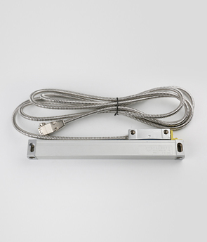
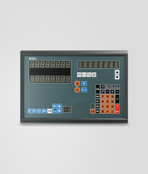
3) Encoder: encoder output represented incremental displacement encoder pulse signal, and with the symbol. Based on the detection principle, the encoder can be divided into optical, magnetic, inductive and capacitive. The method according to the scale and form of the output signal, divided into incremental encoders and absolute encoders. As a robot displacement sensors, photoelectric encoder the most widely used.
Photoelectric encoder works shown in Figure 3, the disc is regularly engraved with translucent and opaque lines on both sides of the disk, the light emitting element and a photosensitive member placed. When the disk rotates, the photosensitive element receives flux changes in synchronization with the light-transmitting lines, the photosensitive element output waveform after shaping has become of the pulse encoder with signs, one pulse per revolution output. In addition, the direction of rotation is judged, the code disk also provides a phase difference of 90o two pulse signals, as shown in FIG.
The difference absolute encoder and incremental encoder that the disc translucent, opaque line graphics, the absolute encoder can have several codes, according to the coding read code on the disc, to detect the absolute position. The design can be encoded binary code, cyclic code, twos complement, and the like.
Magnetization of the recording magnetic encoder scale ruler equally spaced on the surface of a ferromagnetic material, is placed next to the ruler relative magnetoresistance effect element or a Hall element that can detect changes in magnetic flux. Compared with the optical encoder, magnetic encoder scale interval large, but it has oil-resistant, impact resistance and other characteristics. It is expected that a magnetic encoder and a high-resolution optical encoder can be used as soon as possible within the sensor robot.
(3) velocity, angular velocity measuring velocity, angular velocity measurements are essential to drive the feedback control part, sometimes using the measured displacement sensors measure the speed and the amount of displacement detection unit sampling time, and then use the F / V converter into analog voltage, but this approach has its limitations, at low speeds, there is a risk of instability; and high speed, can only get a lower accuracy.
The most common speed, angular velocity sensor is a tachometer generator or become a tachometer sensor, rate generator. The constant magnetic field coil displacement, the rate of change of the induced voltage E across the coil and the inner coil interlinkage magnetic flux φ is proportional to the output voltage is E = -dφ / dt
According to this principle, measuring the angular velocity of the tachometer generator, according to its structure is divided into MOTOR AC tachometer generator and AC induction tachometer generator.
(4) With the rapid acceleration measurement than robots, high precision, by the moving parts of machinery vibration problems caused by insufficient rigidity mentioned at the beginning of the agenda. In order to solve the vibration problem, sometimes mounted on the robot arm movement and other locations acceleration sensor for measuring vibration acceleration, and put it back to the drive. The acceleration sensor is divided into:
1) strain gauge acceleration sensor: strain gauge acceleration sensor vibration system consists of a leaf spring supporting the weight of the composition. Leaf springs are attached at both sides of the two gages, strain gages by vibration, changes its resistance value by the output voltage of the bridge circuit is detected.
2) Servo Accelerometer: servo acceleration sensor system vibration displacement is converted into a weight proportional to the current, the current feedback to the constant magnetic field coil so that hammer back to the original state of zero displacement. According to F = ma = ki
Thus, according to the detected current acceleration can be obtained.
3) The piezoelectric accelerometer sensors: accelerometer sensor using piezoelectric material having a piezoelectric effect, converts the acceleration voltage, i.e.,
U = Q / ACP = dijF / CP
a = UCP / dijFm
Where CP-- piezoelectric element capacitance;
dij-- piezoelectric constant;
U-- voltage;
m-- quality.
(5) In addition to other commonly used internal sensors inside the sensor described above, there are a number of robots installed according to different requirements of different functions inside the sensor, such as for liquid tilt angle measurement of tilt angle sensor, the electrolyte tilt angle sensor vertical transducer tilt angle sensor for measuring the azimuth gyroscope and geomagnetic sensor. These sensors need to be further improved, and better for the robot.
 Previous:The encoder application in gravity meter Next:What is the structure and working principle of the robot encoder?
 Products