


- Changchun Rongde Optics
- Co.,Ltd.
- Add:No.1666 Yaan Road,
- North Lake Development District,
- Changchun 130102,China
- Tel:86-431-81881745
- Mobile:+86 15843030327
- E-mail:rongdecui@roundss.net
- Skype:adacui_roundss
Grating ruler Installation instructions !
Changchun Rongde Optics Co.,Ltd. Release time:2016/7/8 Browse:1365Grating ruler Installation instructions
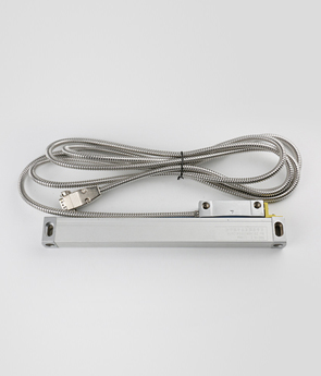
Grating ruler displacement sensor installation is more flexible, can be installed in different parts of the machine tool.
Usually the main 'installed on the machine tool workbench (board), according to the machine tool feeding movement, reading head fixed on the bed, as far as possible the reading head installed in the main down to the bottom of the feet. The installation must pay attention to the choice of the chip, cutting fluid and the oil splashed down direction. If due to the restriction on the installation location must adopt the way of reading head up when installation, must increase the auxiliary sealing device. In addition, under normal circumstances, the reading head should be installed on the relative stationary parts machine tool, the output wire does not move easily fixed, body and feet should be installed on the motion machine parts (such as skateboarding).
1, the grating ruler displacement sensor is installed base
When installing raster ruler displacement sensor, which can not be directly sensor installed on rough machine tools, more can't install on render lacquer of machine tools. The main grating ruler and reading head respectively installed on the machine tool of relative movement of two parts. With a dial gauge check the machine the workbench's main scale installation face parallel to the direction of motion of the guide rail. Dial gauge fixed on the bed, moving workbench, requirements of parallelism is 0.1 mm / 1000 mm or less. If you cannot meet this requirement, a grating ruler base to design processing.
Base required: (1) should add a root and grating ruler ruler body length equal base (base grows best grating feet around 50 mm). (2) the base by milling and grinding process, ensure the plane parallelism within 0.1 mm / 1000 mm. In addition, still need to process a base such as reading head base with feet. The base of the reading head and scale body base shall not be greater than the total error of plus or minus 0.2 mm. When installation, adjust the reading head position, achieve reading head and grating ruler ruler of parallelism is about 0.1 mm, the spacing between grating ruler reading head foot body for about 1 ~ 1.5 mm.
2, the grating ruler displacement sensor main scale installation
Lord will grating ruler with M4 screw installed in the machine tool of the workbench face, but don't tightening, the dial gauge fixed on the bed, moving workbench (main feet and workbench mobile) at the same time. Lord ulnar plane is measured with a dial gauge and guide direction of parallel machine tool, adjust the feet M4 screw position, satisfies the main ruler parallel within 0.1 mm / 1000 mm, the M2 screw tightening up completely.
When installing a main grating ruler, attention should be paid to the following three points:
(1) in the main rule, such as installing more than 1.5 M above the grating, not like a bridge type only install two end, it remains to be in the Lord 'feet and supported. (2) installed in a base case, had better use a clamp stuck 'body midpoint (or points). (3) cannot install the clamp, had better use glass glue live grating ruler body, make the base feet from the main ruler fixed well.
3, the installation of grating ruler head displacement sensor readings
When installing a reading head, first of all should make sure that the reading head base meet installation requirements, and then install the reading head, its installation method and the main ruler is similar. Adjust the reading head finally, make reading head with grating ruler parallel guarantee within 0.1 mm, the reading head and the main foot clearance control within 1 ~ 1.5 mm.
4, the grating ruler displacement sensor spacing device
Raster displacement sensor installed, all must limit device installed in the machine tool guideway, lest machine tool processing product mobile reading head on both ends of the main ruler collision, so as to damage the grating ruler. In addition, the user raster displacement sensor, the choose and buy should choose as far as possible beyond machine tool processing size 100 mm or so of grating ruler, to leave allowance.
5, the grating ruler displacement sensor check
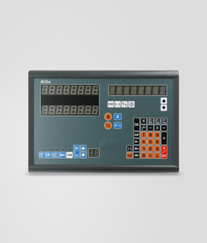
Raster displacement sensor after the installation, can be connected to digital display table, moving workbench, observe whether digital display table count is normal.
A reference position on the machine tool selection, moving back and forth working point to the selected location. The digital display table reading should be the same (or back to zero). Also can use dial indicator or dial indicator, dial gauge with digital display table to zero at the same time (or memory starting data), back and forth many times after the return to the initial position, observe the digital display table data are consistent with dial gauge.
Through the above work, the grating ruler line displacement sensor installation is completed. But for general machine tool processing environment, iron filings, cutting fluid and oil. Sensors, therefore, should be attached with shield, shield is designed according to the shape of the sensor section enlarge leave space of certain dimensions, shield usually USES the rubber seal, waterproof and oil proof capability.
 Previous:The working principle fo digital readout(DRO) Next:Roundss 20 gear angle switches electronic 16 position rotary switch
 Products