


Roundss News

- Changchun Rongde Optics
- Co.,Ltd.
- Add:No.1666 Yaan Road,
- North Lake Development District,
- Changchun 130102,China
- Tel:86-431-81881745
- Mobile:+86 15843030327
- E-mail:rongdecui@roundss.net
- Skype:adacui_roundss
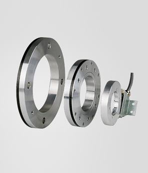
MECHANICAL INTERFACE OF ROTARY ENCODER!
Changchun Rongde Optics Co.,Ltd. Release time:2016/7/28 Browse:1063The primary mechanical interface concerns that influence encoder accuracy and life are the encoder mount and the mechanical coupling. The encoder mount entails the aligning and securing of the encoder to the encoder mounting surface. Alignment is guided using concentricity and perpendicular to the center of rotation, usually the encoder
shaft which can be either a female or male type. The tolerances which must be used are generally dictated by the encoder type. Although, best results are achieved when tolerances are kept to a minimum, regard less of what type is used. Mounting tolerances may become tighter as the performance characteristics enhance. A pilot circle is usually provided on the encoder housing which when utilized will automaticallyconcentrically align the encoder shaft to the center of the encoder mounting surface pilot interface circle. All bolt circle mounting patterns are concentric to the center of rotation as well. Absolute ncoder mounting faces are always perpendicular to the center of rotation. Securing the encoder can be done by using either a bolt circle pattern provided on the incremental encoder mounting face or by using servo clips for a synchro mount. The latter allows the encoder to be rotated and adjusted to user preferred encoder body orientation.The primary objective of the coupling is to accurately transmit the input motion to the encoder without subjecting the shaft to excessive loads (as specified for each product). Excess loads will damage the shaft bearings inducing premature bearing failure as well as increased potential for introducing encoder error. In addition to static loads, care must be taken to ensure that momentary or shock loads do not exceed specifications. The most common methods of coupling the mechanical input motion to the rotary encoder are
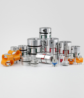
• flexible coupling
• rack and pinion gearing
• gear-to-gear
• toothed belt
The flexible coupling (see Figure 5-8) is the most tolerant to misalignment and is the most accurate for transmission of mechanical input. Both these attributes make the flexible coupling the most commonly
used.
 Previous:the drawbacks of Shaft encoder detecting the angular displacement Next:High quality Pulse controller Handwheel DC5V CNC accessory
 Products