


- Changchun Rongde Optics
- Co.,Ltd.
- Add:No.1666 Yaan Road,
- North Lake Development District,
- Changchun 130102,China
- Tel:86-431-81881745
- Mobile:+86 15843030327
- E-mail:rongdecui@roundss.net
- Skype:adacui_roundss
Company News
Current position :Home > News > Photoelectric Sense
Phase Alignment of Servo Motor Incremental Encoder!
Changchun Rongde Optics Co.,Ltd. Release time:2016/11/15 Browse:1068Incremental encoder output signal for the square wave signal, but also can be divided into commutation signal for the incremental encoder and general incremental encoder, the general incremental encoder with two-phase orthogonal square wave Pulse output signals A and B, and the zero signal Z; commutation signal with the incremental encoder in addition to the output signal with ABZ, but also have mutual difference of 120 degrees of electronic commutation signal cycle number of each motor rotor Of the magnetic pole pairs of the same. The phase alignment between the phase of the UVW electronic commutation signal and the rotor magnetic pole phase and electrical angle phase of the incremental encoder with commutation signal is as follows:
1. Using a DC power supply to the motor through the UV winding is less than the rated current of the DC, U into, V out, the motor shaft is directed to an equilibrium position;
2. Observe the U-phase signal and Z-signal of the encoder with an oscilloscope; adjust the relative position of the encoder shaft and the motor shaft or the relative position of the encoder housing and the motor housing according to the convenience of operation;
3. While adjusting, watch the encoder U-phase signal edge, and Z signal, until the Z signal is stable at high level (in this default Z signal is normally low), lock the encoder and the motor relative Position relationship; back and forth to reverse the motor shaft, let go, if the motor shaft free to return to equilibrium position each time, Z signal can be stabilized at a high level, the alignment is valid.
After removing the DC power supply, verify the following:
The U-phase signal of the encoder and the UV-ray back-EMF waveform of the motor can be observed with an oscilloscope; the U-phase signal of the motor shaft and the encoder are coincident with the zero-crossing of the UV-back EMF waveform of the motor; The Z signal also appears at this zero crossing.
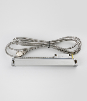
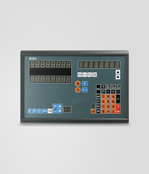
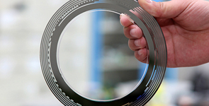
hybrid encoder, non-magnetic encoder, multi-turn encoder, multi-turn combination encoder, draw wire encoder, digital readout, linear scale
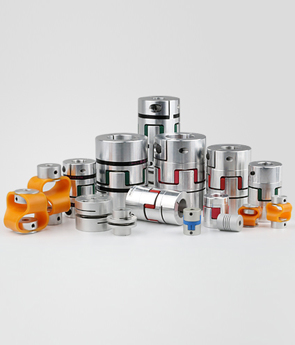
 Previous:DC24V manufacturer rotary encoder string potentiometer analog sensor Next:Encoder accessory aluminium camlock coupling
 Products