


- Changchun Rongde Optics
- Co.,Ltd.
- Add:No.1666 Yaan Road,
- North Lake Development District,
- Changchun 130102,China
- Tel:86-431-81881745
- Mobile:+86 15843030327
- E-mail:rongdecui@roundss.net
- Skype:adacui_roundss
Company News
Current position :Home > News > Photoelectric Sense
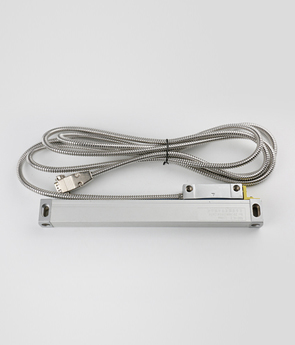
Installation Instructions of linear scale!
Changchun Rongde Optics Co.,Ltd. Release time:2016/3/9 Browse:1112Installation Instructions of linear scale
Installation grating line displacement sensor is flexible, it can be installed in different parts of the machine.
Usually the main scale installed in the worktable (skateboard), the random tool path and move the bed, reading head is fixed on the bed, as far as possible so that the reading head is mounted below the main foot. Select the installation must pay attention to its chips, coolant and oil splashes direction. If the mounting position when the reading mode must be head-on installed, it must increase the secondary seal. In addition, under normal circumstances, the reading head should be installed on the opposite stationary machine part, the output wire does not move easily fixed, and the body should be installed at the foot opposite the machine moving parts (such as skateboarding).
1, grating linear displacement sensor mounting base
When installing grating sensor, the sensor can not be directly mounted on the machine body rough, but can not be installed in the base of the machine body paint. The grating of the main scale and reading head are mounted on two members relative movement of the machine. Parallel with the direction of the scale mounting surface of the machine table and check the dial gauge rail movement. Dial gauge fixed on the bed, moving table, is required to achieve parallelism within 0.1mm / 1000mm. If you can not meet this requirement, we need to design and manufacture a grating base.
Base required: (1) should be added with a grating ruler of equal length of the base body (preferably base grow about 50mm scale). (2) the base by milling, grinding processing procedures to ensure that within its plane parallel 0.1mm / 1000mm. In addition, the need to process a high base of ruler and reading head base. The base and the base of ruler readhead total error no larger than ± 0.2mm. When installed, adjust the reading head position to achieve parallelism of the scanning head and scale of ruler is about 0.1mm, pitch reading head and body between the grating ruler is about 1 ~ 1.5mm.
2, grating linear displacement sensor main scale installation
The machine installed in the mounting surface of the table, but not on the main scale grating with M4 screws, the dial gauge fixed on the bed, the moving platform (the main scale and the table while moving). When the dial gauge measuring scale plane parallel to the main direction of movement of the machine tool guide, adjust the position of the main scale M4 screws, so that the main scale parallelism meet within 0.1mm / 1000mm, the M2 screw completely tightened.
When you install the grating of the main scale, we should note the following three points:
(1) When loading the main scale, such as the installation of more than 1.5M above the grating, can not be installed at both ends of the head just like a bridge type, there is still need support throughout the main body of the foot in the foot. (2) In the case of the base case is installed, it is best to use a clamp stuck midpoint of ruler (or a few). (3) can not be installed card midnight, it is best to live with adhesive glass scale body, the base ruler and the main scale fixed.
3, installation of grating line displacement sensor reading head
When installing the scanning head, we should first ensure base surface reading head reaches the installation requirements, and then install the scanning head, the installation method is similar to the main scale. Finally, adjust the reading head, so that the reading head and the grating of the main scale parallelism ensure that within 0.1mm, its reading head and the main scale clearance controlled within 1 ~ 1.5mm.
4, the grating line displacement sensor limiter
After grating linear displacement sensor fully installed, be sure to install limit devices on the machine guide, so as not to clash head to the main scale reading ends, thereby damaging the grating when machining product movement. In addition, users in the purchase of the grating line displacement sensors, should try to use beyond the machining dimensions of about 100mm grating to the left margin.
5, grating linear displacement sensor checks
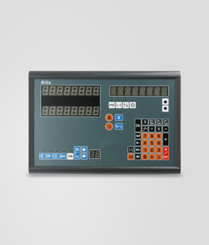
After grating linear displacement sensor installed, it can be connected to digital form, move the table, observe the DRO counts are normal.
Select a reference position on the machine, the operating point moves back and forth to the selected location. DRO readings should be the same (or homing). It may also be using a dial (or dial), so that the dial gauge and DRO simultaneously to zero (or memory initial data), after serving several returns to the initial position, and observe the digital display micrometer whether the data table consistent.
Through the above work, grating line displacement sensor installation is complete. But for general machining environment is concerned, iron, cutting fluids and oil more. Thus, the sensor should be accompanied by the installation of a guard sensor is designed in accordance with the shape of a cross-sectional enlarged left some space to determine the size, usually a rubber seal cover, it has a waterproof anti-oil capacity.
 Previous:optical grating transducer working principle Next:Linear scale detection and data processing
 Products